This is an old revision of the document!
Table of Contents
Power Quality Analyzer
Requirements
- 3-phase voltage, current, frequency, measurement
- active, reactive, apparent power, power factor
- neutral current
- harmonics analysis up to 50th order
- quality - swell, dip, interruption, transient/over voltage, inrush current, unbalance rate
- real-time operation
- USB communication interface
REST API
"api/v1/values"
{
  "U1": 240.0,
  "U2": 241.0,
  "U3": 242.0,
  "I1": 1.0,
  "I2": 2.0,
  "I3": 0.5,
  "fi1": 10.0,
  "fi2": -1.0,
  "fi3": 90.0
}
"api/v1/samples.csv"
i1,  i2,  i3,  u1,  u2,  u3
93390, -361519, 129825, 5145535, -774099, -4559377
19145, -338362, 153637, 5365310, -1620378, -3868587
-6606, -323890, 150418, 5446114, -2413114, -3135951
-3541, -304116, 174229, 5479039, -3169516, -2380155
...
esp-idf for ESP32-S3 installation and configuration
$ mkdir ~/esp
$ cd ~/esp
$ git clone -b v5.5.1 --recursive https://github.com/espressif/esp-idf.git
$ cd esp-idf
$ ./install.sh esp32s3
- pqa project configuration
$ cd ~/projects.local/elektro/pq-anal/fw/pqa
- activate build environment - v5.5.1
$ . ~/esp/esp-idf/export.sh
- activate build environment - v6.1.0
$ . ~/.espressif/tools/activate_idf_v6.1.sh
- proceed with pqa project configuration
$ vim main/idf_component.yml
$ cat main/idf_component.yml
## IDF Component Manager Manifest File
dependencies:
...
espressif/esp-dsp: '*'
$ idf.menuconfig
  * Partition Table ---> Partition Table (Single factory app (large), no OTA)
  * Serial flasher config ---> Flash size (8MB)
  * Component config ---> ESP PSRAM ---> [*] Support for external, SPI-connected RAM
  * ---> SPI RAM Config ---> Mode (QUAD/OCT) of SPI RAM chip in use (Octal Mode PSRAM)
  * ---> SPI RAM Config ---> SPI RAM access method (Make RAM allocatable using malloc() as well)
  * ---> SPI RAM Config ---> (1024) Maximum malloc size, in bytes, to always put in internal memory
  * ---> SPI RAM Config ---> Allow .bss segment placed in external memory
  * Component config ---> ESP System Settings ---> CPU frequency (160MHz)
  * Component config ---> LWIP ---> SNTP ---> (2) Maximum number of NTP servers
  * Component config ---> DSP Library ---> DSP Optimization (ANSI C)
  * Component config ---> DSP Library ---> Maximum FFT length (4096)
- build, flash and monitor
$ idf.py fullclean
$ idf.py build ; echo $?
$ idf.py -p /dev/tty.usbmodem11101 flash
$ idf.py -p /dev/tty.usbmodem11101 monitor
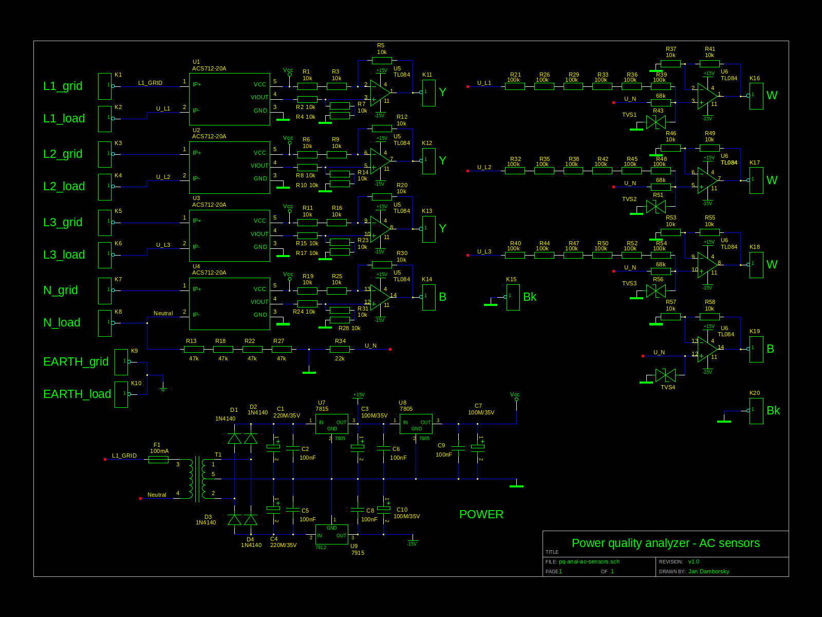
AC sensors
AC voltage sensors
For three-phase balanced system, the sum of instantaneous values of phase voltages (as well as currents) is zero: $$v_{L1} + v_{L2} + v_{L3} = i_{L1} + i_{L2} + i_{L3} = 0$$ In such case also $$u_{N1} = u_{N2} = 0$$ and $$v_1 = v_{L1}\frac{R_{12}}{R_{11} + R_{12}}$$
SPICE simulation
Voltage divider for measuring phase voltages - SPICE simulation schema
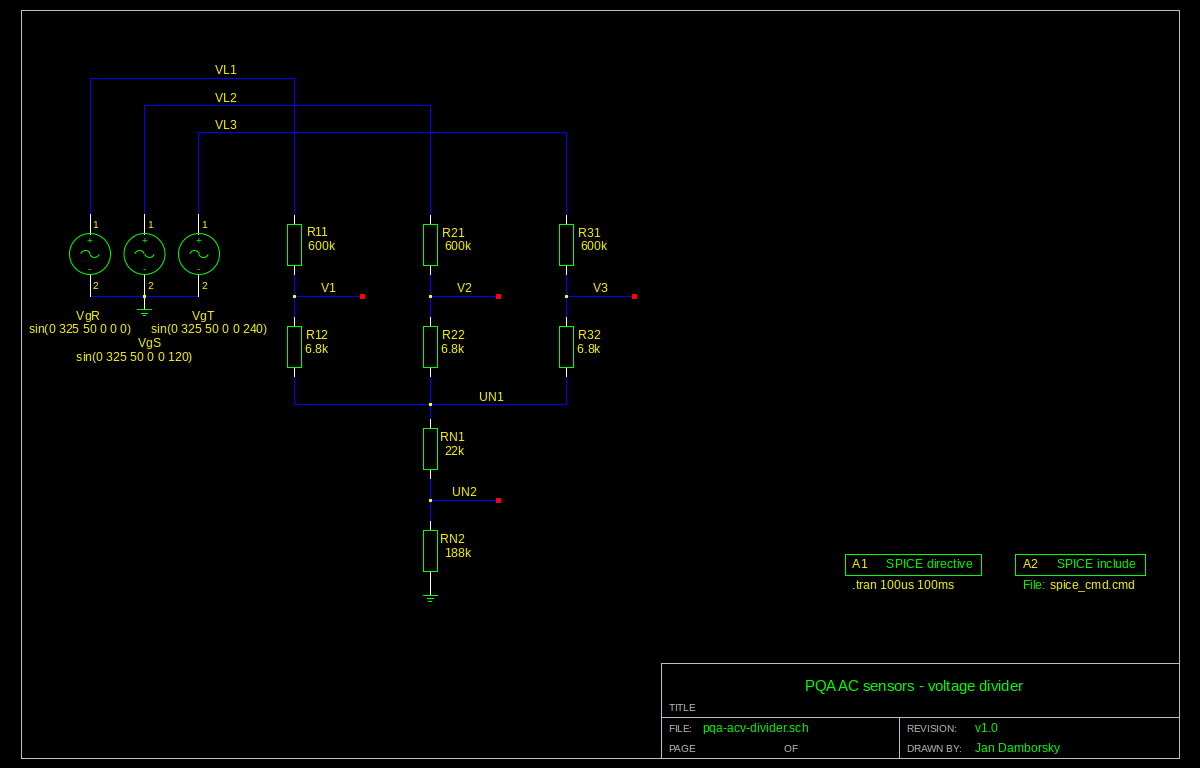
Normal grid conditions

Phase VL3 disconnected

VL2 & VL3 phases disconnected (only VL1 connected)

Power supply
| Component | Max. consumption [mA] | # | Total consumption [mA] |
|---|---|---|---|
| ACS712 | 13 | 4 | 52 |
| TL064 (TL084) | 1 (12) | 2 | 2 (24) |
| 78xx/79xx | 6 | 3 | 18 |
| Total | 72 (94) |
Schema
AC sensors